Control Panel
The following switches and LEDs are located on the SYS-212B-N2T server control panel.
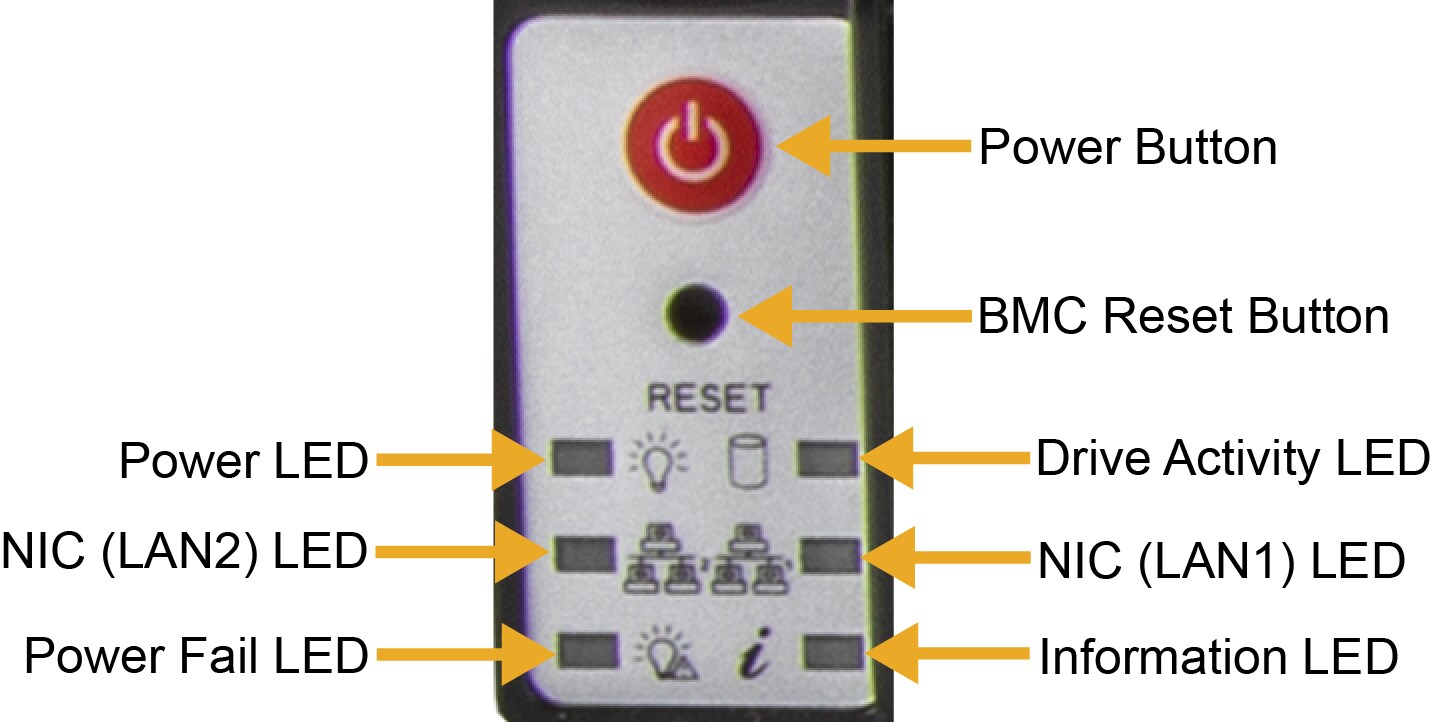
Figure 2. SYS-212B-N2T Control Panel
|
Control Panel Features |
|
|---|---|
|
Feature |
Description |
|
Power Button |
This button applies or removes primary power from the power supplies to the server but maintains standby power. |
|
BMC Reset Button |
This button resets the BMC when pressed. |
|
Power LED |
This LED indicates power is being supplied to the system power supply units. This LED is illuminated when the system is operating normally. |
|
Drive Activity LED |
This LED indicates activity on the storage drives when flashing. |
|
NIC (LAN1) LED |
This LED indicates network activity on LAN1 when flashing. |
|
NIC (LAN2) LED |
This LED indicates network activity on LAN2 when flashing. |
|
Power Fail LED |
This LED indicates a power supply module has failed. |
|
Information LED |
This LED alerts operator to several states, as noted in the table below. |
|
Information LED |
|
|---|---|
|
Color, Status |
Description |
|
Red, solid |
An overheat condition has occurred. |
|
Red, blinking at 1 Hz |
Fan failure; check for an inoperative fan. |
|
Red, blinking at 0.25 Hz |
Power failure; check for an inoperative power supply. |
|
Red, solid with Power LED blinking green |
Fault detected. |
|
Blue and red, blinking at 10 Hz |
Recovery mode. |
|
Blue, solid |
UID has been activated locally to locate the server in a rack environment. |
|
Blue, blinking at 1 Hz |
UID has been activated via BMC to locate the server in a rack environment. |
|
Blue, blinking at 2 Hz |
BMC is resetting. |
|
Blue, blinking at 4 Hz |
BMC is setting factory defaults. |
|
Blue, blinking at 10 Hz with Power LED blinking green |
BMC/BIOS firmware is updating. |