Control Panel
The switches and LEDs located on the SYS-822GA-NGR3 server control panel are described below.
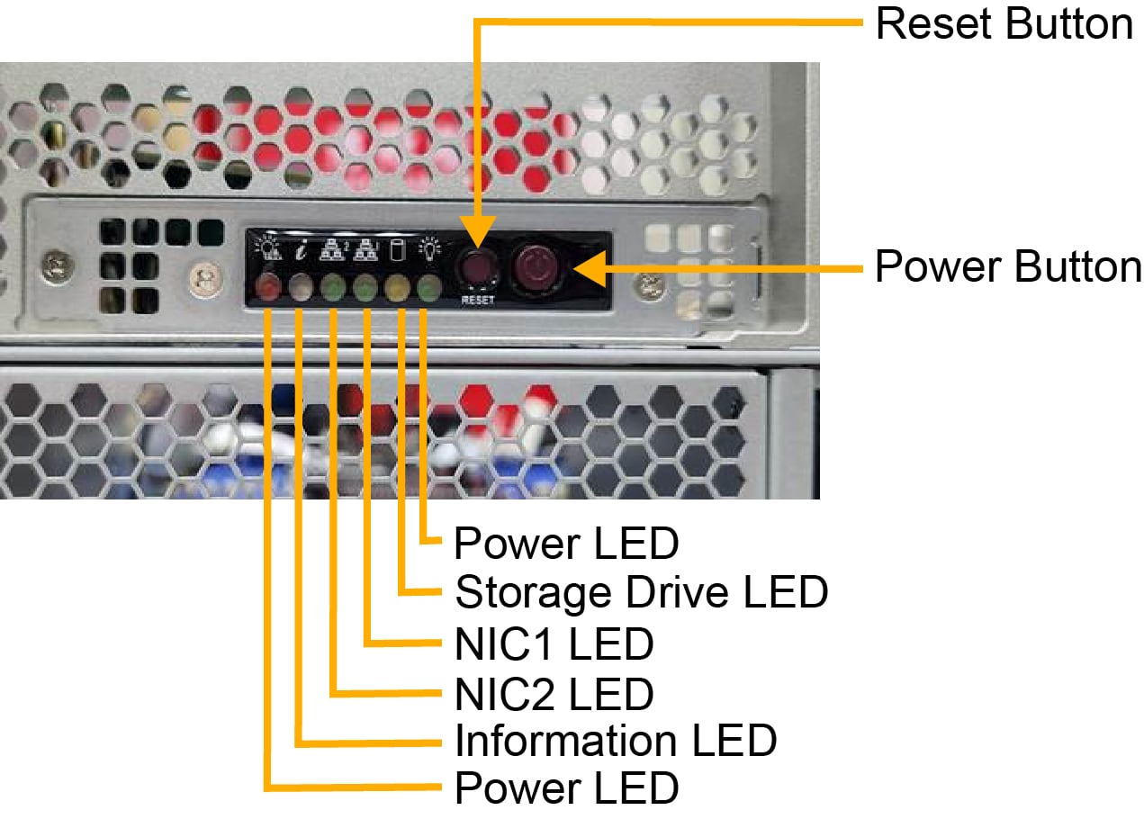
Figure 3. Control Panel
|
Control Panel Features |
|
|---|---|
|
Features |
Description |
|
Power LED |
One LED that indicates if the system is powered on |
|
Storage Drive LED |
One LED that indicates activity on the installed storage devices |
|
NIC1 and NIC2 LED |
Two LEDs that indicate activity on the corresponding LAN1 or LAN 2 connection on the installed AOC cards |
|
Information LED |
One LED that indicates system failure, UID, BMC, or RoT status |
|
Power Fail LED |
One LED that indicates a power failure |
|
Reset Switch |
One reset switch |
|
Power Button |
One power button to power the system on or off |
Power Button
|
Action |
Result |
|---|---|
| Press | Turns the DC power (also known as "main power") on or off |
| Hold 4 seconds | Forces a shutdown |
Power LED
The Power LED (green) indicates the state of the system power and is coupled with the Information LED to indicate the status of various RoT functions.
|
Function |
Status |
Description |
|---|---|---|
| Power | Steady ON | DC power (main power) is on |
| RoT | Blinking at 4 Hz, with Information LED flashing blue at 10 Hz | BIOS firmware is updating |
| RoT | Blinking at 4 Hz | Checking BIOS/BMC integrity |
| RoT |
Blinking, two blinks at 4 Hz, 1 pause at 2 Hz (with Information LED flashing blue at 10 Hz) Essentially a blink pattern at 4 Hz of on-on-off-off, repeating |
BMC firmware updating |
| RoT | Blinking at 1 Hz (with Information LED solid red) | Fault detected |
Storage Drive LED
When flashing, the Storage Drive LED (amber) indicates activity on the installed storage devices. Only activity on storage devices connected to the PCH will be reflected on the Storage Drive LED. These devices include NVMe drives in drive bays cabled to the PCH (but not an HBA) and the M.2 NVMe internal storage devices.
The storage activity associated with other HBAs or NVMe drives can be monitored on the drive carriers.
NIC1 and NIC2 LEDs
When flashing, the NIC1 and NIC2 LEDs (green) indicate activity on the corresponding LAN1 or LAN 2 connection on the installed AOC cards.
On 1U systems, the LAN1 LED will reflect the activity on AIOM port 1. Activity on the other AIOM ports will not cause LED activity on the front panel. Similarly, on 2U systems, the LAN1 LED corresponds to port 1 on the AIOMs, and LAN2 corresponds to port 2 on the AIOMs. Activity on additional ports, such as port 3 and port 4, will not be reflected on the front panel.
In addition to the front panel LAN1 and LAN2 LEDs, the AIOM module will have individual Link and Activity LEDs.
These Link and Activity LEDs follow the guidelines outlined in the OCP 3.0 specification, which allows for the uniformity of operation across all OCP 3.0 products. The guidelines include color, luminous intensity, and functional requirements. Please refer to the OCP 3.0 specification for more information.
Information LED
The Information LED (blue, red) is a bi-color LED that communicates information about failures, UID, BMC, and RoT status in the system. See the summary table below. Some status definitions are coupled with the Power LED status to differentiate between different states in the system.
|
Function |
Status |
Description |
|---|---|---|
|
Failure |
Red, solid |
An overheat condition has occurred. |
|
Red, blinking at 1 Hz |
Fan failure, check for an inoperative fan. |
|
|
Red, blinking at 0.25 Hz |
Power failure, check for a non-operational power supply. |
|
|
UID |
Blue, solid |
UID has been activated locally to locate the server in a rack environment. |
|
Blue, blinking at 1 Hz |
UID has been activated remotely using the BMC to locate the server in a rack environment. |
|
|
BMC |
Blue, blinking at 2 Hz |
BMC is resetting. |
|
Blue, blinking at 4 Hz |
BMC is setting factory defaults. |
|
|
RoT |
Red, solid with Power LED blinking |
Fault detected. |
|
Blue, blinking at 10 Hz with Power LED blinking |
BMC or BIOS firmware being updated. The Power LED blink pattern identifies which firmware is being updated. |
|
|
Blue and red, blinking at 10 Hz |
Recovery mode. |