MCLAG Combination of Layer 2 and Layer 3
In some deployments, both Layer 2 and Layer 3 MCLAG are deployed. In most setups inter-VLAN routing will be required. If your setup requires inter-VLAN routing, then the Layer 3 routing is a prerequisite, so configure Layer 3 routing either using static routes or by using a dynamic routing protocols. All the IP addresses should be reachable. The routing is out of scope of this section; for routing, see Layer 3 Configuration.
MCLAG Configuration Combination of Layer 2 and Layer 3: IPv4
Configuring MCLAG requires the following steps, which must be followed on both the MCLAG peer switches.
-
Create port-channels.
-
Create VLANs.
-
Remove IP addresses associated with the relevant interfaces.
-
Add port-channel members.
-
Add VLAN members and assign IP addresses.
-
Create MCLAG domain and assign unique IP.
-
Add member port-channels to the MCLAG domain.
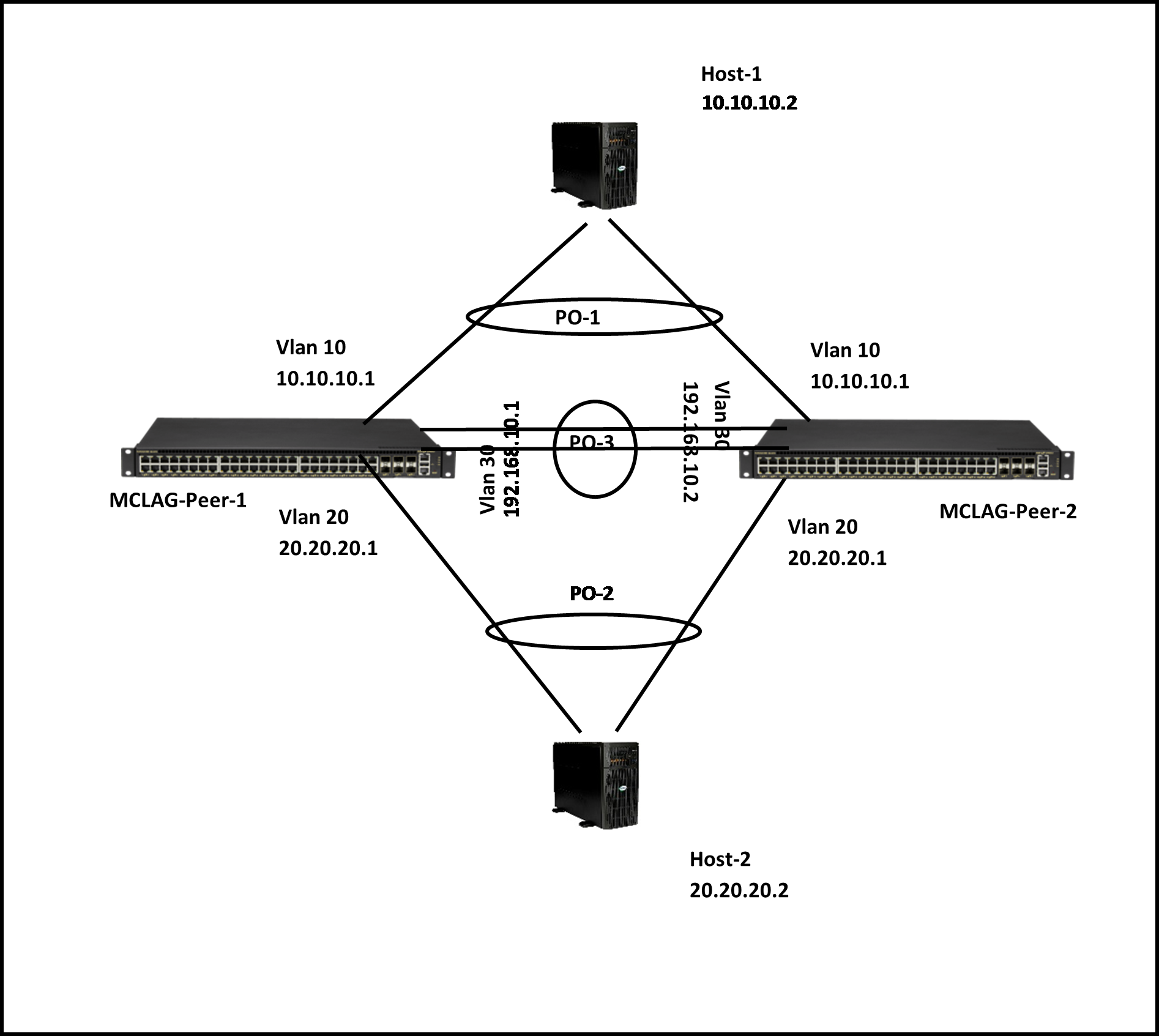
Figure 15. Sample Combination of Layer 2 and Layer 3 MCLAG Topology: IPv4
Step 1: Create Port-Channels
For details on creating port-channels, see Link Aggregation. The example given below is for quick reference. This step must be completed on both MCLAG peer switches.
An example command to create port-channels is given below.
|
MCLAG Switch 1 |
MCLAG Switch 2 |
|---|---|
|
config portchannel add PortChannel01 |
config portchannel add PortChannel01 |
|
config portchannel add PortChannel02 |
config portchannel add PortChannel02 |
|
config portchannel add PortChannel03 |
config portchannel add PortChannel03 |
Step 2: Create VLANs
For details on creating VLANs, see VLAN. The example given below is for quick reference. This step must be completed on both MCLAG peer switches.
An example command to create VLANs is given below.
|
MCLAG Switch 1 |
MCLAG Switch 2 |
|---|---|
|
config vlan add 10 |
config vlan add 10 |
|
config vlan add 20 |
config vlan add 20 |
|
config vlan add 30 |
config vlan add 30 |
Step 3: Remove IP Addresses Associated with Relevant Interfaces
The interfaces on SONiC, by default, are configured as routed ports. The interfaces have default IP addresses that must be removed to make them function as Layer 2 ports. The following command is used to remove the associated IP addresses. This step must be completed on both MCLAG peer switches.
An example command to remove IP address is given below.
|
MCLAG Switch 1 |
MCLAG Switch 2 |
|---|---|
|
config int ip rem Ethernet48 10.0.0.96/31 |
config int ip rem Ethernet48 10.0.0.96/31 |
|
config int ip rem Ethernet49 10.0.0.98/31 |
config int ip rem Ethernet49 10.0.0.98/31 |
|
config int ip rem Ethernet53 10.0.0.106/31 |
config int ip rem Ethernet53 10.0.0.106/31 |
Step 4: Add Port-Channel Members
For details on adding port-channel members, see Link Aggregation. The example given below is for quick reference. This step must be completed on both MCLAG peer switches.
An example command to add port-channel member ports is given below.
|
MCLAG Switch 1 |
MCLAG Switch 2 |
|---|---|
|
config portchannel member add PortChannel01 Ethernet48 |
config portchannel member add PortChannel01 Ethernet48 |
|
config portchannel member add PortChannel02 Ethernet49 |
config portchannel member add PortChannel02 Ethernet49 |
|
config portchannel member add PortChannel03 Ethernet53 |
config portchannel member add PortChannel03 Ethernet53 |
Step 5: Add VLAN Members and Assign IP
For details on adding member ports to a VLAN, see VLAN. For details on configuring IP, see Interface Properties. The example given below is for quick reference. This step must be completed on both MCLAG peer switches.
An example command to add VLAN members and configuring VLAN IP is given below.
|
MCLAG Switch 1 |
MCLAG Switch 2 |
|---|---|
|
config vlan member add 30 PortChannel03 |
config vlan member add 30 PortChannel03 |
|
config vlan member add -u 10 PortChannel01 |
config vlan member add -u 10 PortChannel01 |
|
config vlan member add -u 10 PortChannel02 |
config vlan member add -u 10 PortChannel02 |
|
config vlan member add 10 PortChannel03 |
config vlan member add 10 PortChannel03 |
|
config int ip add Vlan30 192.168.10.1/24 |
config int ip add Vlan30 192.168.10.2/24 |
Step 6: Create MCLAG Domain and Assign Unique IP
The MCLAG domain must be created; the MCLAG domain will be identified with the domain-id. The IP address of the port-channel, which will serve as the peer-link, will be used as source IP address. The IP address from the MCLAG peer switch on the other end of the peer-link port-channel will be used as the destination IP address. The unique-ip will be used to forward MCLAG control-traffic to the peer switch. This step must be completed on both MCLAG peer switches.
Follow the below steps to create MCLAG domain and assign the unique-ip.
|
Step |
Command |
Description |
|---|---|---|
|
1 |
config mclag add [OPTIONS] <domain_id> <source_ip_addr> <peer_ip_addr> <peer_ifname> |
Add an MCLAG domain.
|
|
2 |
sudo config save –y |
Optional: Save the current configuration to be part of the startup configuration. |
An example command to create an MCLAG domain is given below.
|
MCLAG Switch 1 |
MCLAG Switch 2 |
|---|---|
|
config mclag add 1 192.168.10.1 192.168.10.2 |
config mclag add 1 192.168.10.2 192.168.10.1 |
|
config mclag unique-ip add Vlan3 |
config mclag unique-ip add Vlan3 |
Step 7: Add MCLAG Member Port-Channels to the MCLAG Domain
After the MCLAG domain is created, the MCLAG port-channels must be added to the MCLAG domain. This step must be completed on both MCLAG peer switches.
Follow the below steps to add member port-channels to the MCLAG domain.
|
Step |
Command |
Description |
|---|---|---|
|
1 |
config mclag member add [OPTIONS] <domain_id> <portchannel_names> |
Add an MCLAG domain.
|
|
2 |
sudo config save –y |
Optional: Save the current configuration to be part of the startup configuration. |
An example command to add MCLAG port-channels to the domain is given below.
|
MCLAG Switch 1 |
MCLAG Switch 2 |
|---|---|
|
config mclag member add 1 PortChannel01 |
config mclag member add 1 PortChannel01 |
|
config mclag member add 1 PortChannel02 |
config mclag member add 1 PortChannel02 |
MCLAG Configuration Combination of Layer 2 and Layer 3: IPv6
Configuring MCLAG requires the following steps, which must be followed on both the MCLAG peer switches.
-
Create port-channels.
-
Create VLANs.
-
Remove IP addresses associated with the relevant interfaces.
-
Add port-channel members.
-
Add VLAN members and assign IP addresses.
-
Create MCLAG domain and assign unique IP.
-
Add member port-channels to the MCLAG domain.
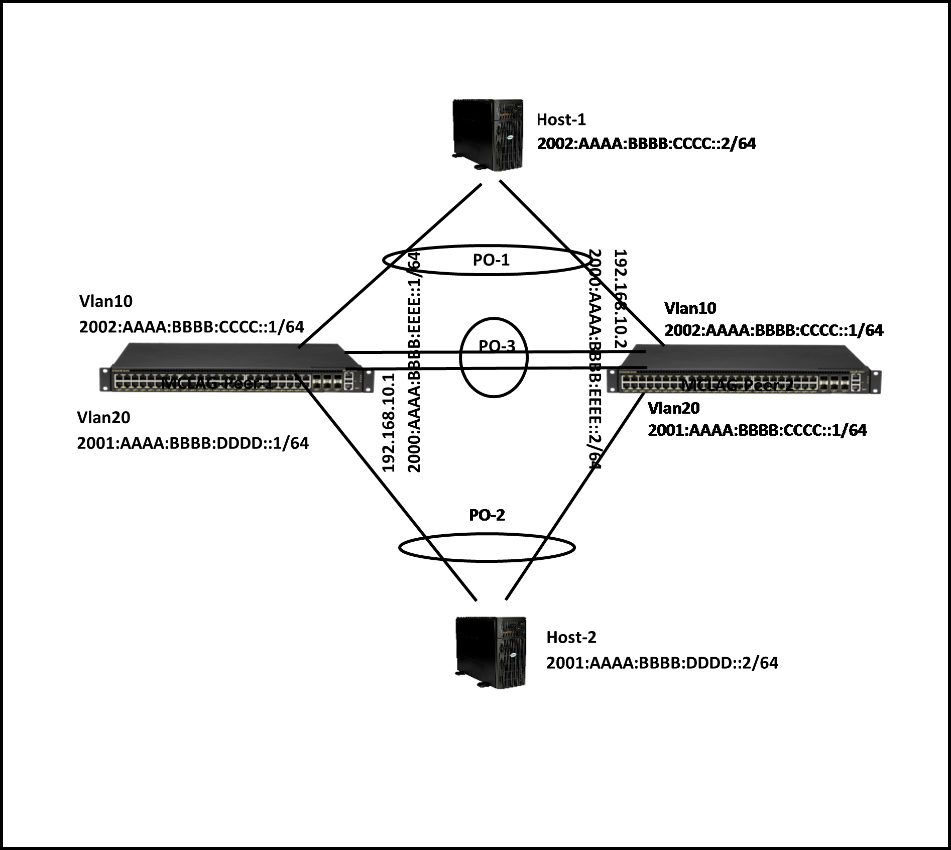
Figure 16. Sample Combination of Layer 2 and Layer 3 MCLAG Topology: IPv6
Step 1: Create Port-Channels
For details on creating port-channels, see Link Aggregation. The example given below is for quick reference. This step must be completed on both MCLAG peer switches.
An example command to create port-channels is given below.
|
MCLAG Switch 1 |
MCLAG Switch 2 |
|---|---|
|
config portchannel add PortChannel01 |
config portchannel add PortChannel01 |
|
config portchannel add PortChannel02 |
config portchannel add PortChannel02 |
|
config portchannel add PortChannel03 |
config portchannel add PortChannel03 |
Step 2: Create VLANs
For details on creating VLANs, see VLAN. The example given below is for quick reference. This step must be completed on both MCLAG peer switches.
An example command to create VLANs is given below.
|
MCLAG Switch 1 |
MCLAG Switch 2 |
|---|---|
|
config vlan add 10 |
config vlan add 10 |
|
config vlan add 20 |
config vlan add 20 |
|
config vlan add 30 |
config vlan add 30 |
Step 3: Remove IP Addresses Associated with Relevant Interfaces
The interfaces on SONiC, by default, are configured as routed ports. The interfaces have default IP addresses that must be removed to make them function as Layer 2 ports. The following command is used to remove the associated IP addresses. This step must be completed on both MCLAG peer switches.
An example command to remove IP address is given below.
|
MCLAG Switch 1 |
MCLAG Switch 2 |
|---|---|
|
config int ip rem Ethernet48 10.0.0.96/31 |
config int ip rem Ethernet48 10.0.0.96/31 |
|
config int ip rem Ethernet49 10.0.0.98/31 |
config int ip rem Ethernet49 10.0.0.98/31 |
|
config int ip rem Ethernet53 10.0.0.106/31 |
config int ip rem Ethernet53 10.0.0.106/31 |
Step 4: Add Port-Channel Members
For details on adding port-channel members, see Link Aggregation. The example given below is for quick reference. This step must be completed on both MCLAG peer switches.
An example command to add port-channel member ports is given below.
|
MCLAG Switch 1 |
MCLAG Switch 2 |
|---|---|
|
config portchannel member add PortChannel01 Ethernet48 |
config portchannel member add PortChannel01 Ethernet48 |
|
config portchannel member add PortChannel02 Ethernet49 |
config portchannel member add PortChannel02 Ethernet49 |
|
config portchannel member add PortChannel03 Ethernet53 |
config portchannel member add PortChannel03 Ethernet53 |
Step 5: Add VLAN Members and Assign IPs
For details on adding member ports to a VLAN, see VLAN. For details on configuring IP, see Interface Properties. The example given below is for quick reference. This step must be completed on both MCLAG peer switches.
An example command to add VLAN members and configuring VLAN IP is given below.
|
MCLAG Switch 1 |
MCLAG Switch 2 |
|---|---|
|
config vlan member add 30 PortChannel03 |
config vlan member add 30 PortChannel03 |
|
config vlan member add -u 10 PortChannel01 |
config vlan member add -u 10 PortChannel01 |
|
config vlan member add 10 PortChannel03 |
config vlan member add 10 PortChannel03 |
|
config vlan member add -u 20 PortChannel02 |
config vlan member add -u 20 PortChannel02 |
|
config vlan member add 20 PortChannel03 |
config vlan member add 20 PortChannel03 |
|
config int ip add Vlan10 2002:aaaa:bbbb:cccc::1/64 |
config int ip add Vlan10 2002:aaaa:bbbb:cccc::1/64 |
|
config int ip add Vlan20 2001:aaaa:bbbb:dddd::1/64 |
config int ip add Vlan20 2001:aaaa:bbbb:dddd::1/64 |
|
config int ip add Vlan30 192.168.10.1/24 |
config int ip add Vlan30 192.168.10.2/24 |
|
config int ip add Vlan30 2000:aaaa:bbbb:eeee::1/64 |
config int ip add Vlan30 2000:aaaa:bbbb:eeee::2/64 |
Step 6: Create MCLAG Domain and Assign Unique IP
The MCLAG domain must be created; the MCLAG domain will be identified with the domain-id. The IP address of the port-channel, which will serve as the peer-link, will be used as source IP address. The IP address from the MCLAG peer switch on the other end of the peer-link port-channel will be used as the destination IP address. The unique-ip will be used to forward MCLAG control-traffic to the peer switch. This step must be completed on both MCLAG peer switches.
Follow the below steps to create MCLAG domain and assign the unique-ip.
|
Step |
Command |
Description |
|---|---|---|
|
1 |
config mclag add [OPTIONS] <domain_id> <source_ip_addr> <peer_ip_addr> <peer_ifname> |
Add an MCLAG domain.
|
|
2 |
sudo config save –y |
Optional: Save the current configuration to be part of the startup configuration. |
An example command to create an MCLAG domain is given below.
|
MCLAG Switch 1 |
MCLAG Switch 2 |
|---|---|
|
config mclag add 1 192.168.10.1 192.168.10.2 |
config mclag add 1 192.168.10.2 192.168.10.1 |
|
config mclag unique-ip add Vlan3 |
config mclag unique-ip add Vlan3 |
Step 7: Add MCLAG Member Port-Channels to the MCLAG Domain
After the MCLAG domain is created, the MCLAG port-channels must be added to the MCLAG domain. This step must be completed on both MCLAG peer switches.
Follow the below steps to add member port-channels to the MCLAG domain.
|
Step |
Command |
Description |
|---|---|---|
|
1 |
config mclag member add [OPTIONS] <domain_id> <portchannel_names> |
Add an MCLAG domain.
|
|
2 |
sudo config save –y |
Optional: Save the current configuration to be part of the startup configuration. |
An example command to add MCLAG port-channels to the domain is given below.
|
MCLAG Switch 1 |
MCLAG Switch 2 |
|---|---|
|
config mclag member add 1 PortChannel01 |
config mclag member add 1 PortChannel01 |
|
config mclag member add 1 PortChannel02 |
config mclag member add 1 PortChannel02 |
MCLAG Show Commands
The commands to check the MCLAG status and to debug the MCLAG issues are given below.
The following command displays the current state of the MCLAG.
|
mclagdctl dump state |
|
|
|
Example: |
|
The MCLAG's keepalive is: OK |
|
MCLAG info sync is: completed |
|
Domain id: 1 |
|
Local Ip: 192.168.10.1 |
|
Peer Ip: 192.168.10.2 |
|
Peer Link Interface: PortChannel03 |
|
Keepalive time: 1 |
|
session Timeout : 15 |
|
Peer Link Mac: 0c:c4:7a:3e:18:2d |
|
Role: Active |
|
MCLAG Interface: PortChannel02,PortChannel01 |
|
Loglevel: NOTICE |
|
root@sonic:~# |